Common Patch Panel Wiring Errors: Troubleshooting Guide for Smooth Network Operations
Patch panels are the unsung heroes behind a well-organized network, serving as central hubs where cables meet and data flows. But when mistakes happen in patch panel wiring, they can cause all sorts of headaches—dropped connections, interference, and endless troubleshooting. The goal here is simple: to help you understand common patch panel wiring errors, why they matter, and how to prevent or fix them effectively. Let’s break down the biggest errors, offer practical solutions, and set you up with tips to keep your network running smoothly.
Common Patch Panel Wiring Errors
Wiring errors in patch panels may seem small, but they can lead to big issues in network performance. Here’s a breakdown of some of the most frequent errors and how they impact the system.
Incorrect Wiring Scheme
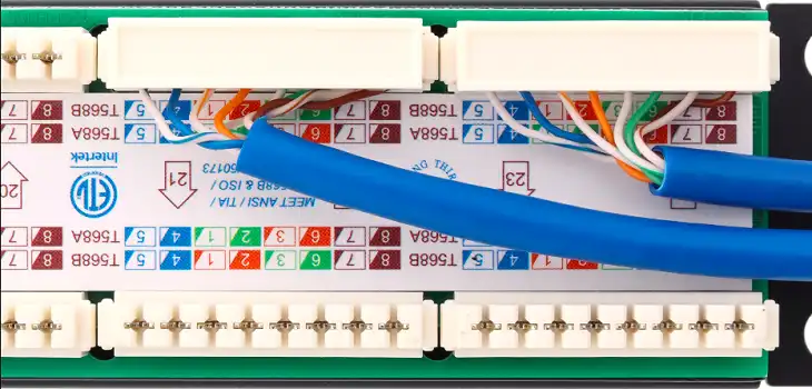
A simple mismatch in the wiring scheme can cause connection issues. Two standards are used for Ethernet wiring: T568A and T568B. Each has a different sequence for pairing cables, and consistency in the chosen standard is crucial.
Mixing T568A and T568B wiring schemes is a common problem, leading to crossed signals and data interference. One user shared that they resolved connectivity problems by correcting a mistake where green and blue pairs were reversed, revealing a T568B error in a T568A setup. To avoid this, it’s essential to use a trusted wiring diagram and double-check connections, ensuring the wiring scheme is uniform across all devices.
Misinterpreting Wiring Diagrams
Misreading wiring diagrams can lead to incorrect terminations, which can scramble the signal path. Common mistakes include confusing brown and blue pairs between standards or flipping wires within pairs, both of which can disrupt signal integrity. One DIY installer shared an example where a diagram switch between the blue and brown pairs led to network drops until they caught the error. Accurate and clear wiring diagrams from reputable sources can prevent these issues.
Physical Installation Errors
The physical setup itself plays a large role in maintaining signal quality. Poorly installed cables can result in loose connections, cable damage, and faulty terminations.
- Loose Connections: If cables aren’t punched down correctly, connections can come loose, creating intermittent connections or data loss. One professional recommended re-terminating loose wires, which often solves connection issues.
- Cable Damage: Tight bends or improper handling during installation can cause breakage within cables. Damaged cables can lead to intermittent connectivity problems and even total connection loss.
- Incorrect Termination: Incorrectly punched down wires can leave some pins unconnected or cause interference between pairs. Checking terminations and ensuring all wires are securely seated can prevent these errors.
Crosstalk and Interference
Crosstalk, or interference between signal-carrying wires, can be a significant issue, especially if cabling is not properly installed or if incorrect components are used. Let’s dive into some examples.
- Using Incorrect Components (e.g., Cat5 vs. Cat6)
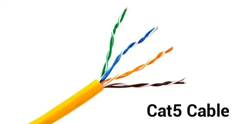
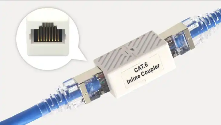
Different Ethernet categories like Cat5 and Cat6 aren’t just marketing terms—they’re designed for different speeds and interference levels. Using Cat5 plugs in a Cat6 setup can lead to problems like data packet loss. For instance, one technician found that Cat5 connectors on a Cat6 patch panel passed initial testing but later showed packet loss during real-world use. Always ensure that all components match the setup’s cabling standard.
- Close Proximity of Connectors
A poorly arranged patch panel can also increase crosstalk. Connectors placed too close together can lead to interference, with one solution being to use every other port on high-traffic panels to minimize the risk.
- Insufficient Cable Length
Short patch cables (under 3 feet) can cause standing wave interference, where the signal bounces back into the cable, creating issues with connectivity. Use patch cables at least 3 feet long to avoid this risk and ensure stable performance.
- Lack of Grounding
Electromagnetic interference from ungrounded racks can wreak havoc on network signals. One forum thread highlighted the challenges of interference and packet loss due to ungrounded equipment. Grounding the patch panel rack can reduce interference, stabilize connectivity, and ultimately extend the life of your setup.
Effects of Wiring Errors on Network Performance
The impact of wiring errors extends far beyond a few dropped connections:
- Data Transfer Issues: Errors can slow down speeds, cause packet loss, or result in full disconnections.
- Increased Interference and Signal Degradation: Poor wiring makes the network more vulnerable to interference, particularly from nearby equipment.
- More Downtime and Maintenance: Incorrect installations require frequent adjustments, resulting in costly and time-consuming maintenance.
- Complex Troubleshooting: Miswiring makes it harder to diagnose network issues, especially in high-density setups.
Best Practices for Avoiding Common Wiring Errors
Investing in the right tools and adopting a systematic approach can prevent most wiring problems.
- Essential Tools: Basic tools for installation include a punch-down tool, cable tester, crimping tool, and wire strippers. These will help ensure solid connections and proper terminations.
- Labeling and Documentation: Always label cables and keep a documented wiring diagram for reference. Clear labels reduce time spent on maintenance and troubleshooting.
- Routine Inspections: Regular checks can identify and fix small issues before they escalate.
- Training: A well-trained team minimizes errors and ensures more consistent installation quality.
Troubleshooting Guide for Common Wiring Errors
Troubleshooting starts with a few basic steps that can quickly uncover most wiring issues.
- Visual Inspection: Check all connections and cables for visible signs of wear, improper seating, or damage.
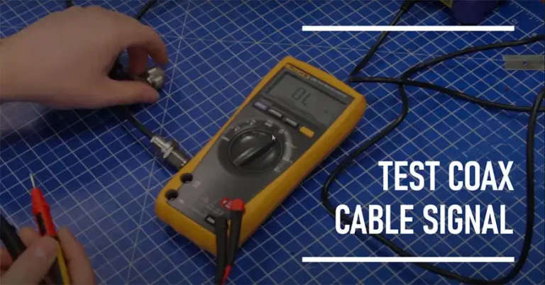
- Cable Testing: Use a cable tester to verify continuity and signal quality. Basic testers measure continuity, while advanced testers can detect interference.
- Cross-Referencing Documentation: Use your original wiring map to identify any deviations.
- Proactive Solutions: Once identified, make corrections promptly and re-test until all connections are stable.
FAQs
What’s the difference between T568A and T568B?
Both are wiring standards for Ethernet, differing mainly in the arrangement of the green and orange pairs. T568B is more common in the US, but consistency within your setup is key.
Can I mix Cat5 and Cat6 in my patch panel setup?
Mixing these can cause issues, especially if high data speeds are required. It’s best to use components that match the setup’s cabling category for optimal performance.
Why do I need grounding for my patch panel rack?
Grounding reduces electromagnetic interference and stabilizes connections, improving network reliability.
What cable length should I use between patch panels?
It’s recommended to use patch cables at least 3 feet long to prevent standing wave interference, which can disrupt signal quality.
Wrapping Up
While patch panels may seem straightforward, they demand care and precision. Common wiring mistakes, from loose connections to mismatched components, can cause frustrating network issues. By following clear wiring diagrams, using the correct components, and ensuring consistent wiring standards, you can build a robust setup that minimizes interference and keeps your network running smoothly.

